This is my All inclusive Airbrush, Crazy Fabrication, and modeling, blog. I Love my airbrush and while I mainly paint miniatures and models, sometimes I branch out a bit on radically different projects. I do take commissions but Im a bit pricey as I invest in my creations. Email me through my webpage thirdfatecreations.com
Finally found an excuse to break out the welder and teach myself to weld. After some initial work on a house project I decided to prototype a battleaxe. Many years ago i made a pair of wooden battle axes for my wife because we saw some she loved at the ren fair but didn't have the disposable to drop on 300 dollar each axes.
So maybe 15 years later I made my first battle axe. This was a good proof of principal on the fabrication techniques and materials. My goal is to make some nicer ones for a later anniversary.
It didn't balance quite right so I lathed and welded a counter weight to the pommel. Then for my birthday a couple days later used it to slice a piñata in half to the delight of my children. Off with its head!
And a few tests in Onward. Don't judge my getting my butt kicked by AI. The recoil hack works well with onward.
EDIT: Note do not use LiIon batteries. The stock kicks too hard and after 10k rounds or so compacts the foil in the batteries. Use a tethered 12V supply parallel to the airline or NiCd NiMH or other batteries proven to take a beating with radio controlled vehicles. (dont use LiPos without great dampening)
First, How hard does it kick. This is difficult to convey so I shot a video of it kicking its own 5 lbs off of a floor.
Now for those considering a compressor...
I thought a bit should be devoted to air sources focusing on the
-compressor
-impedance of the air line
-and on board reservoir
COMPRESSORS:================
The next consideration, or one of your first perhaps, is the air supply. If you have a compressor in your garage, great. but some may not have one or are looking for a replacement, or just don't want to hear that loud thing running in the wee hours of the night. There are many options but one many may not be aware of are the "silent" oil-less compressors.
I originally bought a Eurotec 10A with a <40dB sound level. Awesome for airbrushing but, it needed a tank. So I ripped apart a coleman camping compressor took its motor out and kept the valves, couplings, and <1gallon tank. Strap 2 computer fans on it and you have a compressor that shouldn't be run for more than 20% duty cycle or so that Ive ran for roughly 10 years now at well over 50%, often up to 100% for 2 hrs straight and its still kicking. Just remember to drain your tank.
Tank: If your going to buy a tank and can afford it, get a corrosion resistant one. Never fill it beyond its pressure capacity and make sure you have a pressure switch on the compressor that prevents over pressurization. Most have this already but if you go ripping parts off of your compressor, make sure you don't remove this.
However, if you are in the market for a new compressor a couple lines you should consider for low sound (IE wont drive you or your house mates nuts from the sound) are the
Silentaire line ~30+db --run it anytime
Eagle silent line ~44+db --ok for night time running
California air tools ultra quiet line ~56+dB --daytime only
I would avoid paash and anything that doesn't output at least 60Psi. It will be disappointing.
I believe sparmax is the re branding of the eurotec 10A but it claims only about 40PSI where the pressure gauge I put on my tank says its consistently pumping up to 60PSI. But I think the eagle line seems like the best bang for your buck in pressure, noise, and cost.
Regardless pick the trade offs you can deal with, and make sure it has at least a 1 gallon tank.
AIR HOSE/LINE RESTRICTION:==========
Ok you got your compressor and tank, you now need to get the air supply to the pneumatic cylinder. But airlines have restrictions/impedance and the restrictions are two fold,
1. the ability of the airline to be flexible and not restrict movement during VR play
2. the ability of the air line to deliver CFPM on demand.
Thinner lines tend to be more flexible but greatly restrict flow limiting power at the piston. Feeling the restriction of thicker lines and their affect on your movement may constantly remind you your playing a game, which is less fun.
I recommend a braided hose, either a modified airbrush line or an ultra soft compressor line for the last 4-8ft, then whatever line you can reasonably afford to go from your tank to your rig.
I mount a quick coupler above my head with the cable tether and anchored it to make sure it cant swing down and nail me in the head. The airline regulator is mounted there too for ease of adjustment. I then cut a cheap airbrush braided rubber hose and re-connectorized it for my setup. I then anchored it loosely with para cord to a few points along the sling so in game I barely know its there, I just feel the sling. A few small carabiners on the back of my VR HMD and along the cable management tethers and I quickly snap the airline into place when needed, hook up the quick coupler and Im ready to rock. Also the quick coupler is useful to stop explosive air bleed out when you disconnect.
ON-BOARD RESEVOIRE:================
So making tradeoffs, there is still more restriction in CFPM than Id like limiting the power of the cylinder, especially after the first shot or 3. This can be mitigated a bit, unless your a fan of full auto, by putting a small reservoir on the stock.
I used PVC pipe and end caps, as well as appropriate PVC glue to make a small pressure chamber. Beware, you are making a small pipe bomb so read the instructions and use the glue/welding sludge correctly! You don't want the pressure chamber exploding in your face while playing. Take care and take precautions and don't get anywhere near the published pressure limit of your materials.
Ok we have a device that works and works pretty well... but something is still missing. Got the grip, the trigger, and the recoil... but the nose is left out.
So we make a scent module.
This one takes advantage of the vent gasses and uses the restricted line with a reservoir to make a scent chamber. Simply take some wire mesh (large surface area) roll it up, and burn something (paper, charcoal, fireworks, on it SAFELY. don't burn your house down. do small quantities at a time, very small.
Once you have enough blackened toxins (yes burned stuff is usually toxic so don't overdue it) roll it up and spray some machine or gun lubricant into the mix.
Now seal it up and with every shot you get a faint whiff of motor oil, burned metal, and fireworks... not perfect but noticeable for the immersion.
For an electronic version you could simply put a fan on it to turn on with every firing. Plus the filter and reservoir help to decelerate the mass on the return stroke so its multi use.
Recoil: the big one. -----------------------------------
Soon a product called force tube *Go support their kickstarter* will be releasing an electric recoil. Stated to provide 60N force over what looks like a 1cm throw of an inserted slot in the butt pad. It bumps the shoulder. But my too powerful for fields G36 airsoft GBBR kicks fairly nicely and I wanted something that kicks at least as hard as that. Electronics likely isn't the way to go for a solid kick unless you are using some sequential fired coilgun like solenoid to get the momentum transfer (or impulse). At least not without a huge amount of power and likely a pretty heavy block of copper wire for the solenoids and some powerful ND54+ magnets that need to be sufficiently impact protected.
So looking into it I came up with a design using the following for a
PNEUMATIC RECOIL DEVICE.
So I took my Stock from this.
To this.
Granted I'm now cleaning it up to look nicer, but hey it works beautifully!
And here is how.
The basic parts needed are as follows.
1. Double acting pneumatic cylinder OD 1.125" to 1.5", Stroke 2-5" Cost 20-60USD
NUMATICS, CYLINDER, 1062DG2-02A-05, 1-1/16" BORE, 2" STROKE, PIVOT BUSHING
Longer throw is better but depending on where you mount it you may not be able to have that much length without interfering with a controller or getting recoil at a strange angle. Ideally it impacts the but plate to transfer momentum directly to the shoulder as transferring it just to the rifle stock will likely overpower any magnets you have holding your controllers to the stock. I could see modifications to MAMUT and PROTUBE stocks to allow a kick in one direction to bottom out a stop on the magnet blocks while minimally influencing their effectiveness for rapid release and reattachment, but for now its easier just to put the weight right up against the shoulder.
2. Directional Control Electric Solenoid Air Valve 4 Way 2 Position 1/4 Inch 12V DC 20-40usd
gives about 20ms response which is good.
3. 100ft 1/4" DOT Air Line Bags Air Ride Suspension 100 FT 1/4 inch 100' 30-40usd to connect the compressor to the recoil device. Run it down the cable for the HMD, then along the sling to the stock. A Quick fitting is recommended to detach the sling from the HMD.
4. 5 PCS 1/4" OD x 1/4" NPT Swiveling Elbow Metal Push In to Connect Tube Fitting 10-20usd for nice easy connect/disconnect keeping a fairly low profile.
5. ADJUSTABLE IN LINE PRESSURE REGULATOR FOR PNEUMATIC AIR TOOL,43-87 PSI, 1/4 NPT 20usd
and a bunch of lesser parts.
555 timer
12V - 5V regulator POLOLU 5V 600mA --accept no substitute, this thing is cool and efficient.
Ho31 A57 Nfet
2x 1kohm POT
1x 10kOhm POT
2x 1n4148 diodes
100nf cap--or so
some resistors 1kohm to 10kohm.
NTE3036 phototransistor
prototype board
0.8mm coax wire 1/2ft
1 4mm or 5mm superbright white LED 3-3.4V operation 20mA max
and other random minor circuit components
some zip ties for initial setup
1-1/4" to 1-1/2" OD aluminum tube (or larger) to protect you from the bounce weight.
1 to 1-1/8" steel rod at least 2" long for a bounce weight 8oz with threads to mate to cylinder.
Ability to drill hole in steel rod and cut and drill aluminum tube as protective sleeve
Some creativity and sensibility in how you mount everything.
1/8"OD steel or brass tube 2-3cm long for trigger pivot rod.
1x 4.7mm OD x 3-6mm long ND magnet
1x 1/8" OD 3-5mm long ND magnet
Expendables:
PC7 epoxy
JB weld
liquid electrical tape
hot glue
5min epoxy
superglue
a torch never hurts
Total cost can be as little as 200 dollars, or as much as 400 depending on what you already have and if you buy a spare controller for the hack.--recommended just in case...
------Fire control circuitry:
This is pretty simple.
You hack the haptic controller but stop when you get to the haptic linear oscillator as outlined in part 4.
For the Oculus touch you will find it shorts at 11mA and opens at 3V, so just enough to drive a superbright LED, white with a 3V threshold and 20mA limit. You may need to play around with this but if you get red the breakdown is lower and you need a resistor so you don't over source the controller. If your threshold is too high it just wont light up. Also if you get too low of a threshold diode the diode will light up on haptic pulses for mic presses, slide release, mag release etc, so try to get an LED close to the 3v limit, but still too bright to look at and draws 10mA at 3V (use 2 AA batteries and a DMM to test this) This way the LED filters undesired haptics. Test it in game before closing up the controller for good.
Next remove the haptic and run a 0.8mm coax, or 2 thin silicone wires up through the controller and out to the magnet mount where you will drill a strategic hole and install the LED. now drill a corresponding hole and mount the sensor inline to pick up the signal. I housed the photodiode with a small brass tube for robustness and to reflect extra light. I also installed a tinny 1/16" magnet beside the brass tube to attract the metal can of the photodiode so I can easily remove it for testing and let it snap back in place.
The below circuit takes it from the photodide and converts short and long haptic pulses into a sequence of pulses as long as you tune it. So you have to tune it for the weapon you are using. I find this easily done with one of the two POT's RV1 or RV2. These control the up and down pulse width thereby controlling pulse width and frequency. You typically want your up pulse to be no longer than 20-30ms and your down pulse 30-100ms depending on the weapon your simulating. Since we will put a physical dampener on the return stroke (down pulse) you want it longer so If you are short stroking try turning the down pulse longer and the up pulse shorter.
EDIT: Note do not use LiIon batteries. The stock kicks too hard and after 10k rounds or so compacts the foil in the batteries. Use a tethered 12V supply parallel to the airline or NiCd NiMH or other batteries proven to take a beating with radio controlled vehicles. (dont use LiPos without great dampening) Also lesson learned, You need 12V to drive the solenoid so I used 3 lithium batteries 6000mAh. However! if you use a cheap step-down converter it will likely be inefficient, overheat and fry. I used a Pololu 5V 600mA and it stays nice n cool. other Chinese crap tend to burn out with a drop from 12V to 5V at a few hundred mA. You may need to play with the cap and resistor values but these should be pretty close to what you need for 600-900RPM fire rates.
You may also put an interrupt switch in line with the signal from the 3036 photodiode to the 555 timer pin 4 which is only "on" when the front magnet mount is engaged. This helps further with the white LED to prevent misfires and is quite effective. While I look forward to hacking a Forcetube control board after their kickstarter, you almost don't need to. But the tuning per weapon may get old after a while. It takes 10 seconds typically but may take 2 minutes if your a little slow or didn't design enough range in the circuit PWM with RV1 and RV2 (variable resistors or POTs).
Operational current on standby at 12V is about 15mA and up to about 150mA peak per shot fired. 3 lithium batteries at 6000maH will last a while.
FINALLY A REMINDER ON SAFETY:
You are using 60+Psi to accelerate an 8+ oz mass toward your arm. Make darned sure you have built a sleeve and frame of sufficient robustness so you CANNOT GET HURT. Test fire it on the floor first. A lot! Also make sure the mass impact the frame right against your shoulder, or hits a movable part that hits your shoulder directly to reduce shock waves travelling through the frame and making the accelerometers in the controllers jump.
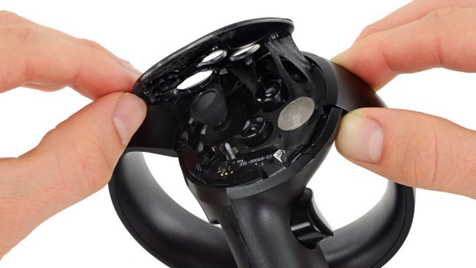
Operating it like the picture below without a mount and without stops is dangerous. Don't do it. Plus without a dampener at the end of each stroke your likely to destroy the cylinder. This particular model had integrated air dampeners. Most dont.
Ok for this, I didnt take very good pictures during my hack so Im going to borrow very liberally from https://www.roadtovr.com/oculus-touch-teardown-disassembly/
and from https://www.ifixit.com/Teardown/Oculus+Touch+Teardown/75109
Also, in retrospect this modification should be done BEFORE part 2 unless your just going to wait for the forcetube kickstarter for the signal board. Most of the pictures initially are from them. However partway through we stop because they take it apart too far for our needs. There are only 4 screws you need to takeout (maybe 5)
Remove the battery cover and battery. Remove the decal. Use a torx screwdriver to remove the screws. I believe 3 are visible at this point. Keep track of lengths and where they go (note taking is a good idea). Photos courtesy iFixit (BY-NC-SA) Now get a thin firm piece of plastic, like a fake credit card trash you get in the mail, sharpen one edge and carefully wedge it around the perimeter of the top plate but only going in about 2 mm so you dont damage anything. Carefully work it around to pry up the top plate. Photo courtesy iFixit (BY-NC-SA) After top cover removal remove this single torx screw only, its deep in there and long, this holds the cover over the haptic. Now pry off the haptic grip cover. Once the cover is off, you can see the haptic with a red and black wire going to it. The haptic is covered with kapton tape (yellow). First carefully remove the wires from the haptic, I snip them at the base of the LOSC/haptic after pulling up the kapton. Then very patiently and slowly and carefully pry out the haptic block. You might be able to just leave it in there but I saw no need. The wire used is something like this from ebay for a few bucks. Hope you like soldering tinny coax wire! Pigtail Antenna Cable RF0.81 IPEX to IPEX Connector Extension Cable 15cm Long From here I soldered the 2 wires to a 0.8mm Diameter coaxial cable just in case I might encounter interference to any bluetooth RF or anything else with a twisted pair. I routed the wire up as per the red path here careful to avoid LED's, and capacitive sensors. Then drilled a small hole out the case next to the LED ring and Liquid electrical taped the wire to the edge of the ring to secure it and a few key points inside away from any electronics, to secure it. Ensure the grip button on the side doesn't smash the wire where it bends around to enter the top plate region. Drill a hole in the plastic cup then line up and drill a corresponding hole in the mating cup. Or do as I did and line it up to one of the finger recess points on the perimeter. I used a brass tube for reflectivity and liquid electrical taped that tube in place. When using glue or liquid electrical tape on the cups either for magnet mounting or led or whatever, be sure to use something like a solid sheet of packaging tape between the cups to prevent gluing them together. Remove the tape 12-24 hrs once the glue has set. Once the wire is secured carefully fit test each panel as you put it back ensuring the touch controller goes back together without interference. Now the pictures start to get uglier. Since Im using a top mount Mamut magnet cup I rout the wire over the top and secure it with liquid electrical tape. The end of the wire gets soldered to a white superbright LED V=3-3.4V. (note earlier how I said it must turn on at 3V and draw about 10mA. be sure of this before soldering that on or you will regret it. Test it in a game to be sure it lights up on a haptic pulse like firing a pistol or rifle.
In the above picture Red is the LED and photodiode. Green is the extra magnet I installed to improve pull away sheer force as I pull the stock into my shoulder. And blue is the epoxy putty I used to brace the mamut more directly to the touch handle so the LED ring was supporting less weight. A bit of epoxy putty also helps at the base of the mamut mount to remove stress from the LED ring and smooth what the index finger feels when you have a 5 lb stock weighing down on your hand. I felt the need to round off the bottom of the mamut a lot so it didn't dig into my finger.
Now, if you did it right every time the haptic should fire for a "shot fired" signal you should get a pulse of light out of the LED. the optical relay if done right is incredibly reliable. The sensing circuit later will have a POT to adjust the sensitivity.
But, while we are here there is one last modification.
To help ensure the recoil device doesn't fire when your not actually shooting, or braced with both controllers, we put an interrupt switch in the front cup. This switch takes almost no pressure to activate and is carefully scewed into the hole we drilled to stick up just enough for the cup to close the switch when the cup is engaged with a controller. This way you have to have both controllers in to have any chance of the recoil device firing. Thus room lights should be even less likely to set it off, and shooting one handed wont set it off and risk the recoil knocking the magnet cup free. I also put a bit of JB weld on the tip of the button so its harder and lower friction so it doesn't snag. I liquid electrical taped the back of the switch as a rubber impact absorber. Try not to impact it.